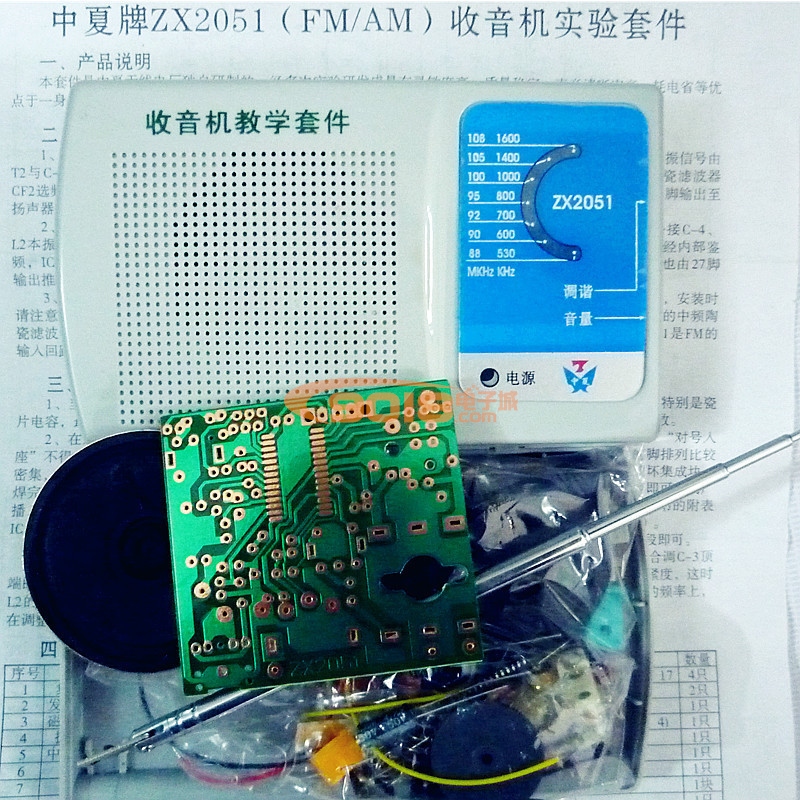
篇一:高频电子线路课程设计报告调幅收音机
课程设计报告
(
题目: 调幅收音机 学生姓名: 陈贵滨 学院: 信息工程学院 系别: 电子系 班级: 通信11-2 指导教师: 黎玉玲、任跃
二 〇一四 年 一 月
目录
第一部分 调幅收音机原理及电路实现 ............................................................... 3 一、调幅收音机原理 .......................................................................................... 3 二、器件的识别及测量 ...................................................................................... 5 第二部分 调幅收音机的仿真与分析 ................................................................. 6 一、仿真注意事项 .............................................................................................. 6 二、单元电路的仿真与分析 .............................................................................. 6 三、 调幅收音机单元电路指标计算、焊接及功能测试 .............................. 15 第三部分 产品验收 ............................................................................................. 20 一、收音机效果验收 ........................................................................................ 20 二、课程设计体会及建议 ................................................................................ 20
第一部分 调幅收音机原理及电路实现
一、调幅收音机原理
图1 收音机电路原理图
该电路从整体上分为三个部分从前至后分别是混频电路、中频放大电路、电压放大及功率放大电路
1.混频电路:广播信号(AM信号)从 T1天线输入经过混频电路后V1和选频网络后电压信号变为465K的放大的电压信号。
图2 输入电磁波时域信号 图3 输入电磁波频谱图
图4 输出电磁波时域信号 图5输出电磁波频谱图
2.中频放大电路:将经过混频放大后的465K的AM信号经过两级高频小信号谐振放大器将mV级的电压信号放大大概100倍左右。再经过V3的三级管包络检波器将AM信号所携带的音频信号从放大后的AM信号中解调出来即得到相应的音频信号。
图6 输入电磁波时域信号图7 输入电磁波频谱图
图8 输出电磁波时域信号 图9 输出电磁波频谱图
3.电压放大及功率放大电路:经过包络检波后的音频信号经过V4组成的低频放大器将音频信号放大后,再通过V5,V6组成的功率放大器将功率放大后驱动扬声器或耳机发声。
图10 输出电磁波时域信号 图11 输出电磁波频谱图
二、器件的识别及测量
表1
篇二:调幅收音机的制作与调试
山西信息职业技术学院
调幅收音机的制作与调试
论文指导教师 所在系别信息工程系学生所在系部信息工程系专业名称应用电子 论文提交日期年 月日 论文答辩日期 年3月 日
2012年 3 月 日
毕业论文(设计)
摘要
随着科学技术的发展,调频收音机的应用十分广泛,尤其消费类占有相当的 市场 。从分离元件组成的收音机到由集成电路组成的收音机,调频收音机技术已 达到十分成熟的地步。从普通的调幅收音机到高级调频收音机,调频收音机以较 高的技术含量和较高的音质得到了广泛的欢迎。 本课题主要研究调频收音机的设计全过程,各部分电路的组成、作用、性能 指标和工作原理。设计方法主要采用了两块集成电路 TA7335P 和 FS2204,使电路 设计变的简单。主要的设计思路是:由天线、输入回路、高频放大电路、混频电 路、本机振荡电路、中频放大电路、鉴频电路、低频功率放大电路、扬声器组成。 本课题设计成果,基本上满足要求,性能指标符合。本电路缺点的是音质噪 声大,电路还有一点失真等等,还需改进。
【关键词】调频收音机发展、调频收音机、调频收音机设计
Abstract
Along with the development of science and technology, FM radios are widely used, especially consumer accounts for a sizeable market. Separation of components from the radio component of the integrated circuit components from the radio, FM radio technology has reached a very mature stage. From the ordinary AM radios to senior FM radios, FM radio to a higher technological content and high sound quality has been widely welcomed. The main research topics FM radio entire process of design, the circuit of the composition, function, performance and principle. Design methods used two IC TA7335P and FS2204, the circuit design of a simple change. The main design ideas : from antenna input circuit, high-frequency amplifier, mixer circuit, the machine oscillation circuit, IF amplifier, Kam-frequency circuit, low-frequency power amplifier, loudspeakers component. Design results of this project, basically meet the requirements with performance indicators. The shortcomings of the circuit noise is the sound quality, there is little distortion circuit, and so on, need to improve.
【Key Words】FM radio, FM radio, FM radio design
目录
前言 ................................................................................................................................................ 1
第一章 收音机的基本工作原理 .................................................................................................... 2
1.1 最简收音机原理 ................................................................................................................... 2
1.2 超外差式收音机原理 ........................................................................................................... 2
第二章 调谐回路 ........................................................................................................................... 5
2.1. 输入调谐回路的作用与要求 ............................................................................................... 5
2.2 输入调谐回路的组成与工作原理 ....................................................................................... 5
第三章 变频回路 ......................................................................................................................... 6
3.1 变频电路的作用与要求 ........................................................................................................ 6
3.2 变频电路的组成与变频原理 ................................................................................................ 6
第四章 中频放大电路、检波和自动控制增益电路 .................................................................... 9
4.1 中频放电路 .......................................................................................................................... 9
4.2 检波和自动控制增益电路 ................................................................................................ 10
第五章 低放级与功放级 .....................................................

5.1 低放级电路 ....................................................................................................................... 13
5.2 功率放大电路 ................................................................................................................... 14
第六章 收音机的安装与焊接 .................................................................................................... 15
6.1 安装注意事项 ................................................................................................................... 15
6.2 易发生的错误 ................................................................................................................... 15
6.3 元件的焊接 ....................................................................................................................... 16
6.4.安装顺序 ............................................................................................................................. 16
第七章 收音机调试流程 ............................................................................................................ 18
7.1 检查电路 ........................................................................................................................... 18
7.2 收音机的调试 ................................................................................................................... 18
7.3 出现的问题 ....................................................................................................................... 19
总结 .............................................................................................................................................. 21
致谢 .............................................................................................................................................. 22
参考文献 ...................................................................................................................................... 23
附录 .............................................................................................................................................. 24
Ⅰ.总原理图 .............................................................................................................................. 24
Ⅱ.元件清单 .............................................................................................................................. 25 Ⅲ. 实物图 ................................................................................................................................ 27
前言
人类自从发现能利用电波传递信息以来,就不断研究出不同的方法来增加通信的可靠性、通信的距离、设备的微形化、省电化、轻巧化等。接收信息所用的接收机,俗称为收音机。目前的无线电接收机不单只能收音,且还有可以接收影像的电视机、数字信息的电报机等。
随着广播技术的发展,收音机也在不断更新换代。自1920年开发了无线电广播的半个多世纪中,收音机经历了电子管收音机、晶体管收音机、集成电路收音机的三代变化,功能日趋增多,质量日益提高。20世纪80年代开始,收音机又朝着电路集成化、显示数字化、声音立体化、功能电脑化、结构小型化等方向发展。
广播电台播出节目是首先把声音通过话筒转换成音频电信号,经放大后被高频信号(载波)调制,这时高频载波信号的某一参量随着音频信号作相应的变化,使我们要传送的音频信号包含在高频载波信号之内,高频信号再经放大,然后高频电流流过天线时,形成无线电波向外发射,无线电波传播速度为3×10⁸m/s,这种无线电波被收音机天线接收,然后经过放大、解调,还原为音频电信号,送入喇叭音圈中,引起纸盆相应的振动,就可以还原声音,即是声电转换传送——电声转换的过程。
篇三:收音机毕业设计报告
摘要 ..................................................................................................... 3
Abstract ............................................................................................. 4
一.设计目的与要求 ........................................................................... 6
二.原理分析 ....................................................................................... 6
2.1发射机原理 ........................................................................... 6
2.1.1 各模块原理分析 ....................................................... 6
2.2.2 BH1417芯片结构和各引脚功能 .............................. 7
2.2.3 protel99se发射原理图的绘制 ............................ 9
2.2.4 PCB板的制作 .......................................................... 10
2.2 接收机原理 ......................................................................... 11
2.2.1调幅工作原理 ........................................................... 11
2.2.2调频工作原理 .......................................................... 13
2.2.3 CXA1691芯片结构和各引脚功能 .......................... 15
2.2.4 protel99se接收原理图的绘制 ............................ 17
2.2.5 PCB板的制作 .......................................................... 18
三.焊接及组装 ............................................................................... 18
3.1 步骤和注意事项 ................................................................. 18
3.2 元器件的摆放 ..................................................................... 20
四.调试 ........................................................................................... 20
3.1 基本调试 ............................................................................. 21
3.2调试中出现的故障、原因及排除方法 .............................. 21
3.3装配完成后,经常出现的问题 .......................................... 22
3.4 分析调试步骤 ..................................................................... 22
五.总结 ........................................................................................... 27
附录 1 ............................................................................................... 28
附录 2 ............................................................................................... 29
参考文献 ........................................................................................... 31
摘 要 本课设从高灵敏度FM/AM教学收音机的组装,原理分析,调试,调试步骤分析几方面对收音机进行了分析说明。用BH1417和CXA1691来实现发射机和接收机。
BH1417是ROHM公司推出的新型FM无线发射芯片,它是由提高信噪比(S/N)的预加重电路、防止信号过调的限幅电路、控制输入信号频率的低通滤波电路(LPF)、产生立体声复合信号的立体声调制电路、调频发射的锁相环电路(PLL)等电路组成。文章给出了 BH1417 的结构、原理、特性。基于 BH1417芯片,配以简单的外围电路,即可实现 FM 无线发射,具有高可靠性和极低的功耗。CXA1691是调频调幅收音机用集成电路。
集成电路凭借体积小、功耗低、可靠性高、性能好以及易于使系统整机实现少调整和不调整等优点,得到了迅速的发展和广泛的应用。收音机也因为集成电路的发展而日渐趋于小型化,这也给其焊接、组装和调试带来了难度。因此须解决在收音机的焊接、组装和调试过程中出现的种种问题,并对其进行分析,这会给收音机的维修带来便捷。
又对其元件组成,元器件摆放,调频调幅原理,调试过程等做了详细解说。了解并掌握这些知识会给我们将来对收音机的组装、调试和维修带来很大便捷。
关键词:发射机;接收机;BH1417;CXA1691
Abstract
This design introduces the high sensitivity FM/AM teaching radio's assembly, the principle analysis, the debugging, the debugging step analyzes several aspects to carry on analysis showing to the radio. Realize the transmitter and the receiver with BH1417 and CXA1691.
BH1417 is the new FM wireless launch chip which ROHM Corporation promotes, it is by enhances the signal-to-noise ratio (S/N) the pre-emphasis, prevents the signal the limiter circuit which, the control input signal frequency low-pass filtering electric circuit moves (LPF), to produce the phase-locked loop electric circuit which the stereo sound serrated signal's stereo sound tone circuit, the frequency modulation launch (PLL) and so on electric circuits to be composed. The article has given the BH1417 structure, the principle, the characteristic. Based on the BH1417 chip, matches by the simple peripheral circuit, then realizes the FM wireless launch, has the redundant reliability and the extremely low power loss. CXA1691 is the frequency modulation amplitude modulation radio uses the integrated circuit.
The integrated circuit relies on the volume to be small, the power loss is low, the reliability is high, the performance good as well as easy to cause the system complete machine to realize the few adjustments and not to adjust and so on merits, obtained the rapid development and the widespread application. The radio also day after day tends the miniaturization because of integrated circuit's development, this also gave its welding, the assembly and the
debugging has brought the difficulty. Must therefore solve all sorts of problems which in radio's welding, the assembly and the debugging process appears, and carries on the analysis to it, this will give radio's service to bring conveniently.
Besides its part composition, the primary device places, the frequency modulation amplitude modulation principle, the debugging process and so on has made the detailed illustration. Will understand and masters these knowledge to give us in the future to radio's assembly, the debugging and the service brings is very greatly convenient.
Keywords:Transmitter,Receiving,BH1417;CXA1691